I’ve been curious about FPGAs since I first heard about them over ten years ago, and over the past month I finally gave them a try for a couple personal projects.
The FPGAs are certainly… different from any other kind of programming, and it took a bit of effort and troubleshooting to get my FPGA calculator working. If you’re interested in getting into FPGAs, here are a few tips below.
1. The basics
Programming FPGAs is different from programming in JavaScript, C#, or C. There are no levels of abstraction between you and the hardware, so it’s essential to learn the foundations of digital logic.
For me, The Art of Electronics worked very well — specifically, chapters 10-14.
The book first introduces the basic logic circuit elements, and then builds up to other components and concepts: flip-flops, clocking, different logic families, logic interfacing, three-state outputs, busses, etc.
Almost all of it was useful when I got to programming the FPGA.
If textbooks are not your thing, there are lots of YouTube videos covering the same subjects.
2. Verilog
There are three main hardware definition languages: Verilog, VHDL, and SystemVerilog. Either one is a valid choice, though I found that for Digilent and Xilinx (my choice of FPGA boards and chips) there were more Verilog examples, so I went with that.
Unfortunately, Verilog just doesn’t have as much great documentation as, say, TypeScript or C#. The best I could find were these two websites:
- Chipverify Verilog Tutorial
- This Verilog guide on readthedocs.io.
I’ve read these before I started programming, and referred back to them a number of times afterwards.
3. The board
You can try buying an FPGA chip and soldering it to a board yourself, but it’s much easier to get a starter board that already includes all the necessary components such as configuration flash memory, USB interface, and voltage regulator.
For starter boards, I liked Digilent boards the most and went with Cmod A7 that had a Xilinx Artix-7 chip on it. It was powerful enough to fit the projects I wanted to build with room to spare, and it could plug into a breadboard.
Alternatively, if you’re looking to spend less, Cmod S7 seems like a decent choice, and if you’re looking for more power, there’s something like Arty A7.
4. Making the LED blink
Now we have everything we need to take FPGA for a test drive.
If you’ve gone with a Digilent board, the next step that worked for me was to go through the Getting started with Vivado guide from Digilent.
Be aware that there are a few quirks that you may run into:
The LED port name in the module definition must exactly match the port name in the constraints file. For example, it can’t be
led[0]in the constraints file andledin the module definitions - you’ll get an error when generating the bitstream.Xilinx wants you to create an account before using Vivado, and they want you to enter something that looks like a real address when doing so. They’ll check the address, but not too thoroughly. You’ll need to log into the account when starting Vivado.
5. Now build your first project.
From here, build whatever you were thinking of.
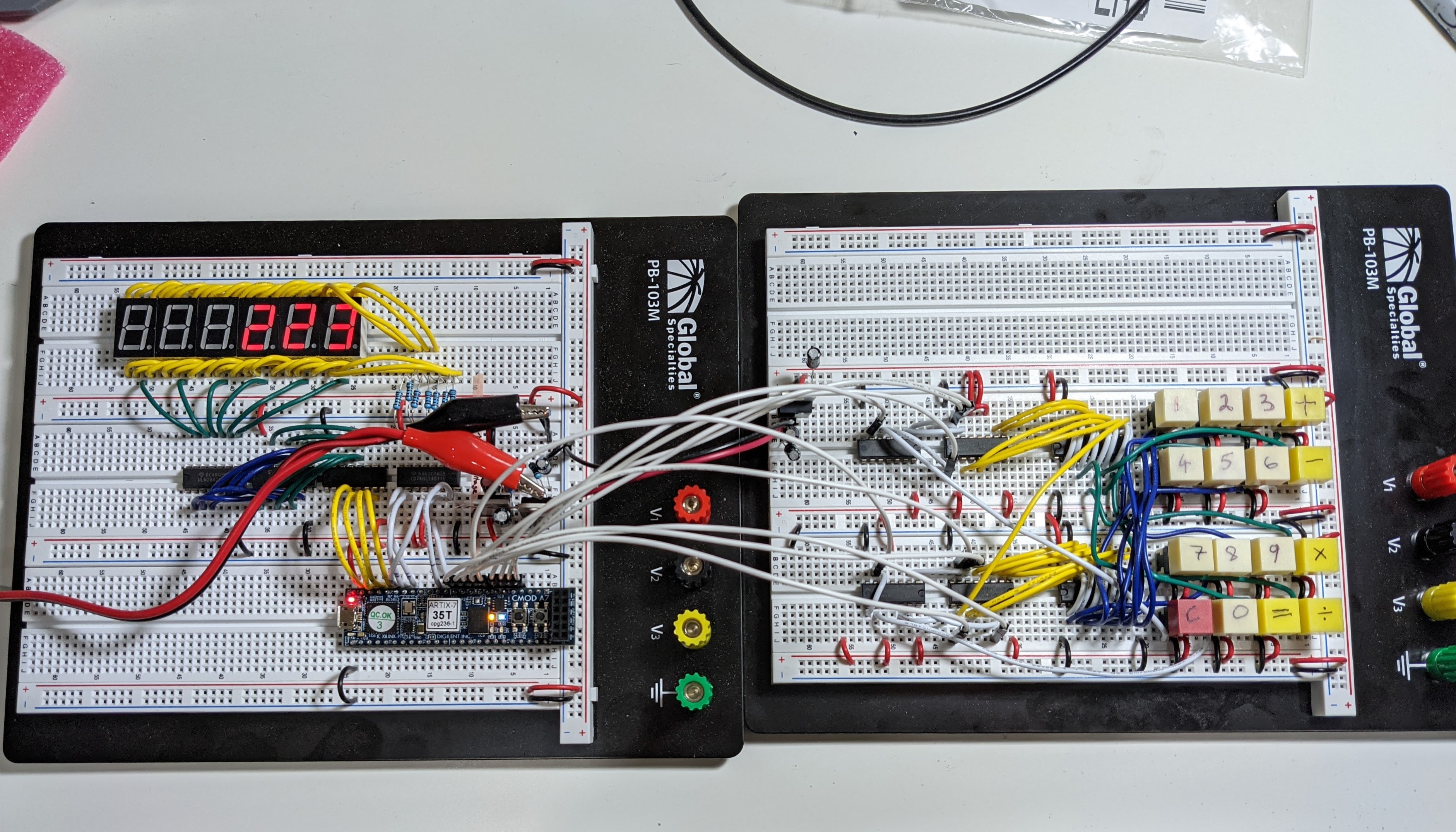
If you’re looking for an idea for a simple project before moving on to something more interesting, I found a calculator to have just the right amount of complexity:
From here on, the things that helped me the most were:
Carefully reading the documentation and the guides, as they often contain the answers you’re looking for. For example, each Digilent board has a detailed reference manual that explains how to work with each component that’s on the board.
The chip manufacturer has detailed guides as well. For example, if you’re looking to change the clock frequency on your FPGA chip, or want to work with multiple clock frequencies, Xilinx has a very thorough guide on working with Mixed Mode Clock Managers.
If you run into a problem, keep simplifying your logic until it starts working. For example, when I was having trouble sending data over the USB/UART link, I ended up removing all of my logic and just tying the RXD (send) wire to TXD (receive) wire to make sure that I could echo the characters through it using the COM terminal. Turns out I couldn’t because I mixed up which wire was the input and which was the output. The rest of my logic was correct.
If you get stuck, like everywhere else, use Google. Someone has run into a similar problem. If you don’t find the exact solution, at least you may get an idea that you can try next.
6. This will save you days
I was going to lump this with the tips above, but this deserves its own section.
Put
1 | `default_nettype none |
at the beginning of every Verilog file (yes, including the backtick), and
1 | `default_nettype wire |
at the end.
This is because by default, if you make a typo in a variable name, Verilog will assume that you’ve defined a new variable of type wire. Because of this, I literally spent a day debugging a problem that was caused by a typo.
If you put `default_type none, Verilog will complain that it doesn’t know the variable type and will bring your attention to the typo.
The closing `default_nettype wire is necessary because apparently some of Xilinx’s own modules (called “IP” in FPGA terminology) rely on implicitly defined variable types.